Shot Management
The primary purpose of BLACS is to execute experiment shots on the lab apparatus. File paths to shots are typically received by BLACS over ZMQ, but can also be loaded directly through the BLACS GUI (either via the file menu, or by dragging and dropping onto the queue). Prior to accepting the shot, BLACS compares the connection table of the shot to the lab connection table and ensures that the shot is compatible with the current configuration of the laboratory hardware. Connection table compatibility requires that the shot connection table is a subset of the lab connection table. This ensures that old experiments can not be run on hardware that is no-longer configured correctly, preventing damage or unexpected results. Shots that pass this check are added to a queue, which is visible in the BLACS GUI (see Fig. 6).
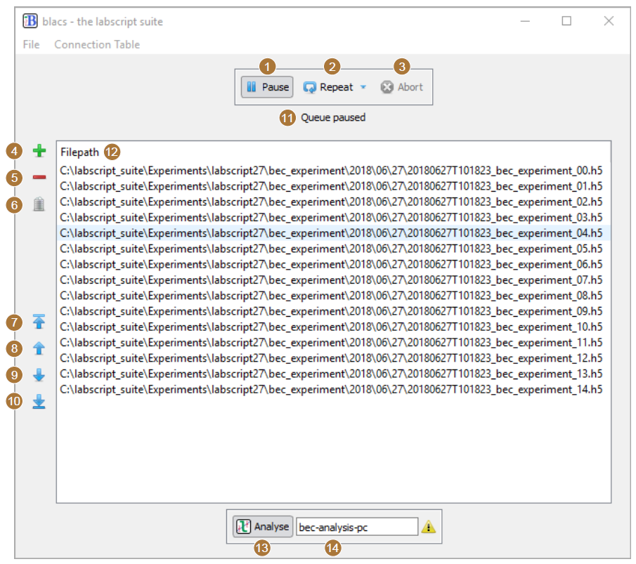
Fig. 6 The queue manager GUI within BLACS (with the device tabs hidden). (1) The pause button stops the queue from processing new shots (a currently running shot will finish). (2) The repeat button, when enabled, will duplicate a completed shot and either place the duplicate at the bottom or the top of the queue (depending on the mode selected). (3) The abort button immediately stops the execution of the current shot and returns hardware to manual mode. (4-5) Buttons to add or delete selected shots from the queue. (6) A button to clear the entire queue. (7-10) Buttons to reorder selected shots within the queue. (11) The current status of the queue is displayed here. For example, the status may indicate that devices are currently being programmed, the master pseudoclock has been triggered and the experiment is running, or that acquired data is currently being saved into the hdf5 shot file. (12) The list of shot files in the queue, in the order they will be executed (the topmost is executed first). (13) A button to enable or disable the forwarding of shots to lyse for analysis. (14) The network hostname of the PC running lyse.
The queue is processed by a thread in BLACS, which we term the ‘queue manager’, that takes the top-most shot in the queue and, in turn, executes it. Shot execution follows the following pattern (a flowchart of this process is also shown in Fig. 7):
For each device in use in the shot, a message is sent to the corresponding device tab state machine indicating that the device should program the device for hardware timed execution of a shot. These messages are sent asynchronously, which ensures devices program in parallel if possible (subject to the state machine being available to process the message). Included in this message is the path to the hdf5 shot file, which each device tab ultimately passes to a worker process that in turn, reads out the hardware instructions and programs the hardware. During this programming, the device tab enters the mode ‘transition_to_buffered’ (see §6.1.1.3).
The queue manager then waits until all devices have reported they have programmed, at which point all device tabs in use should be in the ‘buffered’ state machine mode. If a device does not report it has completed within a 5 minute timeout, or a device reports an error has occurred during programming, the queue manager aborts the shot by pausing the queue, instructing all device tabs to abort, and replacing the shot at the top of the queue.
Provided all devices report they are ready, the queue manager proceeds with starting the shot. This involves recording the current state of all manual controls (as these usually affect the initial values of the shot and may affect results in certain experiments) and then instructing the master pseudoclock to begin execution of the programmed instructions.
The queue manager then waits for the master pseudoclock to report that the experiment shot has completed. If an error occurs in a device tab during a shot, the queue manager aborts the shot (as previously described) and pauses the queue.
Once a shot has completed, the queue manager instructs all device tabs to ‘transition to manual’ mode. At this stage, device tabs enter the ‘transition_to_manual’ state machine mode where they save any acquired data and reprogram the hardware device for manual operation via the BLACS GUI. Again, if errors occur during this process, the queue manager aborts the shot as before, but with the additional step of cleaning any saved data from the hdf5 file (so that the shot file is returned to the state prior to execution).
The path to the shot file is now sent to a separate thread that runs a routine for managing submission of shots to lyse for analysis. This routine forwards the shot file paths to the lyse server specified in the BLACS GUI if analysis submission is enabled (see figure 6.5 (13–14)). If lyse does not respond to these messages, the shot file paths are buffered until such time as lyse does respond, to ensure no shots are missing from analysis.
Finally, the queue manager checks the state of the repeat button in the BLACS GUI and, if required, duplicates the shot (minus the acquired data) and places the duplicate in the appropriate place in the queue.
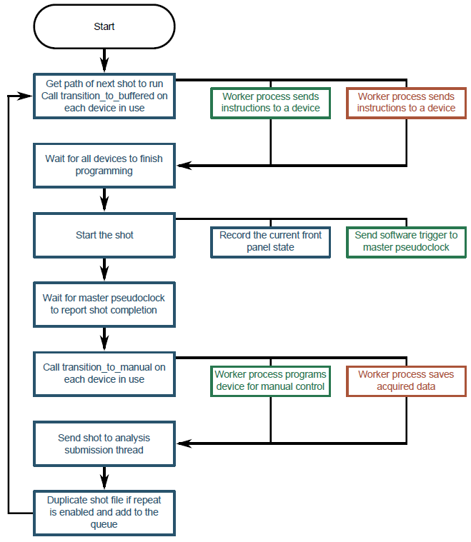
Fig. 7 A flowchart of the logic for the BLACS queue manager. For brevity, we have not included the logic for pausing the queue via the GUI or handling error conditions. See the listing above for further details.