Connection Table
The connection table maps out the way input/output devices are connected to each other in your lab, and the channels (individual inputs/outputs) they have. The devices in your lab should be connected in a similar way to that shown in the figure below.
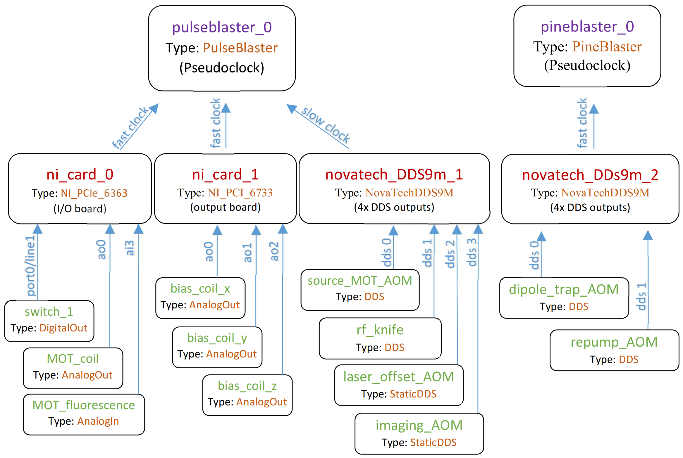
Here we see two PseudoclockDevice instances in the top tier of the diagram. They do not have a parent device that tells them when to update their output (this is true for all PseudoclockDevice instances). However, all but one (the master pseudoclock device) must be triggered by an output clocked by the master pseudoclock device.
Each PseudoclockDevice instance should have one or more Pseudoclock children. Some PseudoclockDevice instances may automatically create these children for you (check the device specific documentation). In turn, each Pseudoclock will have one of more ClockLine instances connected to it. These ClockLine instances generally refer to physical outputs of a device which will be used to clock another device. However, in some cases, one or more ClockLine instances may be internally created for you (check the device specific documentation).
If a device is not a PseudoclockDevice, it must be connected to one via a clockline. such devices inherit from IntermediateDevice. Inputs and outputs are then connected to these devices. For example, DigitalOut, AnalogOut, and DDS. See labscript.outputs and labscript.inputs for a complete list. Note that devices determine what types of inputs and outputs can be connected, see labscript-devices for device information.
If a PseudoclockDevice also has outputs that are not used for a ClockLine, then an IntermediateDevice is internally instantiated, and should be made available through the PseudoclockDevice.direct_outputs attribute (for example see the PulseBlaster implementation).
Note
Most user’s will not need to use PseudoclockDevice, Pseudoclock, and IntermediateDevice directly. These are generic classes that are subclassed by device implementations in labscript-devices. It is these device implementations that you are most likely to use.